Talk to your battery

On notebook batteries controlled by the BQ2092 and BQ2040 (and maybe others)

Contents

Downloads

Either way, you'll need to solder the necessary wiring probes for the parallel port (see below). Be aware that not all parallel port chipsets support the style of abuse employed by the i2c-pport driver. A few specific desktop and server chipsets are known not to work. With the chipsets that do work, you'll need to check your BIOS SETUP - most of the parallel port chipsets are compatible with i2c-pport in the "normal" or "SPP" modes. Notebook chipsets in general seem to be quite tolerant. See the included help.txt for details.

Apart from the utils tailored specifically for the BQ2092 or the BQ2040, there's the generic "eeprom" program (taken from the lm_sensors package) that can be used for reading and writing of any 24cXX i2c EEPROM (24C01 through 24C16), not only in smart batteries but in general.
Speaking of smart batteries, the eeprom util can be used for playing with other gas gauge IC's apart from the two aforementioned models, even with undocumented ones - the only condition is that the gas gauge IC is using an external 24cXX series serial flash EEPROM. This external EEPROM never stores executable code (not even with general-purpose MCU's) - it's barely large enough to hold some callibration parameters and runtime variables that need to be non-volatile. These can be hacked.

WARNINGS:

Schematics of adapters for the i2c-pport driver

The BQ family of gas gauge chips (and probably others) feature two busses that can be tapped: the external SMBus available in the battery connector, and the internal I2C for communication with the Flash EEPROM.
The wiring is almost identical - nevertheless, for easier switch-overs during the refurbishment, I recommend that you make two distinct adapters.

The numbered connector templates have been copied from the excellent Hardware Book web site. The connectors are oriented equal to the scenario where you face the rear side of the PC and gaze at its connectors. Besides, the pin numbers are usually imprinted in the plastic bodies of the connectors.

SMBus - external port

The parallel port pins have the following meanings:
14) SDA
16) SCL
18) ground (this can really be any pin from 18 to 25)


(A photo)

Internal I2C to the EEPROM

This adapter is not quite neceesary for resetting the BQ2092.

24C0XCanon 25
418
514
616
24C0XPS2 keyb.
84
24C0XAT keyb.
85

(A photo)

Note the fine enamel wires for easier wiretapping of the SMT EEPROM.

How to build a custom Linux kernel and install i2c/lm_sensors

If you downloaded the whole CD, you don't need to do this.

If you decide to build from source, you'll need to go through the full kernel build&install procedure:

cd /usr/src/linux      (wherever this symlink points)
make mrproper          (careful, erases .config - make a backup first)
make symlinks
make menuconfig
make dep
make
make bzImage
make modules
make modules_install

Escpecially if you leave module versioning on, the build system generates a new magic number each time you run 'make dep', that is then used to "stamp" (decorate) all symbols in kernel modules. In effect, once you run 'make dep' with module versions on, you'll have to explicitly re-compile and re-install any external modules, e.g. i2c and lm_sensors. Otherwise, upon insmod you get error messages such as "undefined symbol function_name_335cxxt434()."

The kernel + lm_sensors configuration & build instructions are different for Linux 2.2 and for Linux 2.4. My proven-to-work testbeds are RedHat Linux 2.2.14 + i2c-2.6.4 and RedHat Linux 2.4.18 + i2c-2.7.0 + lm_sensors-2.7.0. With some of the details I don't know whether to attribute them to i2c or the kernel, therefore I list them together, the way they worked for me.

The i2c and lm_sensors packages should be available from www.lm-sensors.nu. Note: don't turn ON the original i2c drivers that come with the original kernel sources from your distro - it is strongly recommended that you download the fresh i2c package.

There are about three different ways to compile i2c and lm_sensors - the least disruptive way is perhaps the classic "tar xvzf tarball.tgz", "make" and "make install". This way the package is compiled as stand-alone modules that get installed in the correct place. You have yet to run "depmod -a", which is however typically done automatically by the Linux boot process (at least it works that way in my RedHat).
Alternatively, you can patch the kernel sources and hard-compile the drivers in - which is nevertheless completely unnecessary. The stand-alone modular installation seems safer to the kernel source tree, worked fine for me and the i2c package thus installed works without a hitch.

To be able to compile i2c/lm_sensors, you'll need the following packages installed: python, bison, byacc and flex.

Linux 2.2 + i2c-2.6.4

I recommend that you leave the parallel port driver "ON" and turn the printer driver "OFF". In `make menuconfig', this can be achieved by toggling "general setup"->"Parallel port support" ON, "general setup"->"PC-style hardware" ON and "Character devices"->"Parallel printer support" OFF. In a standard kernel, the printer driver is ON, which causes a failure when you try to load the i2c-pport module ("device in use") - sure, that's because the parallel port is occupied by the printer driver.

You don't need the lmsensors application package - all you need is the bare i2c support in the kernel, i.e. the i2c tarball.

Once we have a kernel without the printer driver, and the i2c modules are installed, we can insert the modules:

modprobe i2c-core
modprobe i2c-dev
modprobe i2c-pport

Worked for me within the following environment:
RedHat 6.2 CZ with a more or less original 2.2.14 kernel and the original GCC compiler (2.91.66). All of that on a Compaq Presario 1622 notebook :)

Linux 2.4 + i2c-2.7.0

It seems that you have to turn parallel port support OFF entirely, in the Linux kernel config.

You need to compile both i2c and lm_sensors.

You need to load the following modules:

modprobe i2c-core
modprobe dmi_scan
modprobe i2c-algo-bit
modprobe i2c-dev
modprobe i2c-proc
modprobe i2c-pport

Worked for me within the following environment:
RedHat 8.0 with a custom 2.4.18 kernel (the original 2.4.18-14, RedHat flavor) and the original GCC compiler (RedHat 3.2-7).
All of that built on a desktop based on VIA KT333 with an Athlon XP 1700+, but I had to actually run the software on different machines, because the VIA KT333's parallel port didn't work for i2c-pport.

Device nodes for i2c

The documentation of the i2c package further describes how to create the "device special files" /dev/i2c* using `mknod', unless you already have them. If you're familiar with mknod, you only need to know the major and minor device number. Try 'cat /proc/devices' to get the major number (and verify that the i2c driver is loaded). The minor numbers start with a zero in ascending order. You'll probably only ever need /dev/i2c0. I myself had the devices ready out of the box which has saved me the hassle with mknod.

The original BQ2092 story

Introduction - of batteries and screwdrivers

This material describes a reasonably simple way to have a nice chat over I2C with "smart" batteries of many notebook brands - which may be a necessary step in a successful battery refurbishment procedure. Is anyone outside of eastern Europe refurbishing notebook batteries, BTW?

Some time ago, I've purchased a second-hand Compaq Presario 1622 - an american model, possibly imported into the Czech Republic already as a pile of trash. It only needed to have its battery refurbished - which seemed to be "no great problem". By the mechanical finish, the battery refurbishment company I've chosen has done a great job - and they've enclosed a neat measurement protocol, certifying perfect condition and capacity. Unfortunately, once inserted back into the notebook, the battery didn't work properly - the notebook would report full charge after five minutes of charging, and full discharge after five minutes of operation on batteries, following up with an immediate shutdown.
As I needed to start to work with the notebook ASAP, I went to a brand service center. "That's the battery. It'll take two days to deliver - your notebook is a U.S. model". I asked them to check the charger inside the notebook, before I pay them an outrageous sum of money for a shiny new battery, that might ultimately be no use if the charger is broken. "Allright, our technician will take a look at it tomorrow. We'll charge you some additional money for the work, and if the bettery replacement doesn't fix the problem, we'll take the battery back." And that's exactly how we did it. It was indeed the battery. No problem that it took them a fortnight to deliver the battery. I didn't even mind coming twice to pick up my notebook just because they didn't have the battery out of stock the first time around (after they'd invited me).
As this was an after-guarantee part replacement / material purchase, I got my "broken" battery back from the service center. So I went to complain about the refurbishment to the refurbishment company. No problem here - they've apologized, reported that they'd found and replaced a misbehaving cell and provided an even neater measurement protocol.
Nevertheless, even after my complaint was thus processed, the battery didn't come back to life. Unfortunately I couldn't find a "battery formatting util" on the web or from friends (as I have found out later, it wouldn't help me anyway - see the technical description below.) So I took it as a challenge and ventured a frontal screwdriver attack at the battery. When I first opened the lid, I had to nod in appreciation upon the mechanical purity of the refurbishment. The refurbishment guys did a great job even on the inside.
The battery had a reasonable voltage, precisely identical across every cell. By the voltage and the typical discharge curve, it was charged to about 70 per cent - even though the notebook was reporting 0 per cent. It was also able to generate reasonable current, without dropping the voltage significantly. Unfortunately my homebrew electronics equipment and limited time didn't allow for a more detailed exploration, such as a proper capacity measurements etc.
I discovered that the battery contained a tiny PCB, with two SMT IC's on it: a larger one (a DIL16 package) and a smaller one (a DIL8). I managed to read the codes: the smaller one was an AT24C02 (clearly an I2C/serial EEPROM by Atmel) and the larger one was a BQ2092. And voila - it's called a "gas gauge", manufactured by Texas Instruments (originally by Unitrode, later acquired by TI), and there's a datasheet available. Cautious optimism :)
It didn't take long to discover that I can talk to the BQ2092 using its SMBUS port. The SMBUS is electrically compatible with I2C, SMBUS commands are a subset of I2C commands. The serial flash contains pre-programmed initial values and some run-time data - so that even if the PCB with BQ2092 loses power, e.g. during a cell refurbishment procedure, the gas gauge IC still remembers the old remaining capacity. The IC can be asked via I2C to perform a reset - later on I discovered that you need to power-cycle the IC to complete the reset (unsolder/resolder the battery of cells from/to the PCB). The I2C flash is connected to a "private" I2C port of the BQ2092 that is not directly accessible at the outer battery connector. The I2C flash could be accessed on the PCB using conductors with some sorta in-circuit probes - this way the gas gauge circuit can be callibrated.
I also remembered that there was some I2C support under Linux. It turned out that most of the software in Linux is written for a myriad of internal PC peripherials, such as heatsink temperature sensors, fan RPM counters, TV and radio tuners and whatever have you. It took me a while to find the parallel port driver by Daniel Smolik. I was also lucky that I already had previous experience with #including conflicting header files in GNU C/C++ - so that I managed to wrestle the direct inclusions of kernel headers within user-space code, which is a prerequisite for using the I2C library functions (macros). And in the end finally I had a nice conversation with my battery - I've retrieved a heap of data out of it, managed to interpret most of it, and finally I've also managed to reset it.

And I was lucky - even the mere reset has woken up the battery to pretty much normal operation :) Even though perhaps it would use some callibration. No time and no equipment for that, though.

For more technical information, read on.

A brief technical description

My battery contains NiMH cells, its nominal capacity is 3800 mAh at 9.6 V (eight cells). The manufacturer is a taiwanese OEM called GLW. Besides Presario 1600, the battery also fits into a Presario 1200. There's also a newer 4,5 Ah model in the same format, and a Li-Ion battery (3.6 Ah at 14.4V ). In other words, it would seem that the built-in charger of the notebook is indeed somewhat smart. GLW manufactures batteries for many different notebook brands and models. Some time ago, I myself was speculating about the outer pinout of a Li-Ion battery in a Compaq Armada M700 that I had in my previous job - the battery is smaller and the shape is different, but the number of pins is identical (five) and so is the power supply voltage (18.5 V), and a few simple electrical measurements were showing similar results to what I have later encountered with my current NiMH battery (that is certainly older by date of manufacture).

The battery is controlled (or perhaps I'd better say "monitored") by a built-in IC called BQ2092, that is communicating with the notebook via SMBus/I2C.

This image is just a poor-quality preview - you can check out the schematic in full quality in the data sheet available from Texas Instruments. You'd better download the datasheet anyway - you'll need it to interpret data read from the battery, if you decide to try that. Somewhere among the application notes on the same web site, there's a generic PCB, amusingly similar to the one I've found in my battery pack - only the current-sensing power resistor is created as a section of a winding thin copper trace, whereas in my battery there's a true discrete SMT device. Apart from the cells and the PCB, the battery pack further contains a discrete thermistor connected to the outer connector (despite the fact that the BQ2092 itself contains a temperature sensor and the value measured is available via I2C) and also a fuse, that's connected in series with the cells and is hidden somewhere among them. Another noteworthy element of the PCB are the four LED's comprising a charge indication bar graph, activated by pressing the "DISPLAY" button.
The TI pages also contain other members of the Unitrode's "gas gauge" family, such as the now deprecated BQ219 or the newer BQ2040 and more - check out the "gas gauges" product folder. The principal I2C communication and probably even the register set should be fairly similar. At the USENET forums there are several reports of the BQ2092 being quite frequent in numerous different batteries. According to the documentation, it can cope with both NiMH and Li-Ion batteries. Therefore it's reasonable to conclude that the information presented here could be useful with many different notebook brands and models.

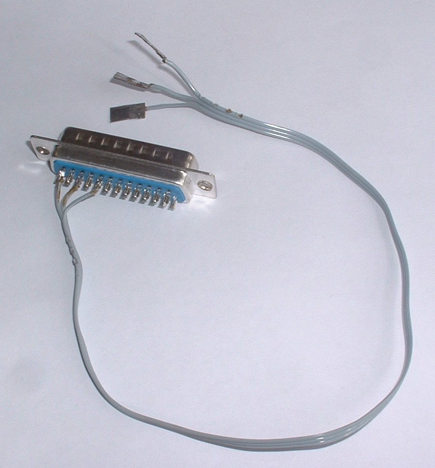
Next, we need to solve how to connect the battery to a computer via I2C. This can be arranged using the parallel printer port - all you need is a male 25pin Canon connector (D-SUB25M), a piece of cable or thin conductors (three strands) and a few pieces of brass of whatever origin, that can serve as makeshift blade contacts against the female battery connector. And of course you need a soldering iron and a piece of tin and resin.

The battery's got five pins - see the picture below. The list below the picture shows their meanings:

  1. +V(batt) = positive battery terminal. This pin goes straight to the positive terminal of the first cell.
  2. SMBC aka SCL (SM Bus Clock, Serial CLock)
  3. SMBD aka SDA (SM Bus Data, Serial DAta)
  4. thermistor(+). Its second leg is connected to ground (pin #5).
  5. Ground = negative battery terminal. Well, almost - between this pin and the negative terminal of the last cell, there's the current-sensing resistor (0.05 Ohms). I.e., the outer pin #5 is connected to the PCB, which is connected straight to the last cell.

This is the pinout at the parallel port (for the i2c-pport driver by Daniel Smolik that's a part of the Linux-based I2C package):

14) SDA
16) SCL
18) ground (in fact this can be any pin between 18 and 25 - all of them are GND)

Tu sum up, the battery connector can be connected to the parallel port in the following way:

BatteryCanon 25
216
314
518

Check the chapter on Kernel compilation on how to roll your own kernel and install the i2c/lm_sensors modules.

Last but not least, we need to talk to the battery. My preferred way to write a simple proggie in C. I tried C++ but the compiler kept repulsing the kernel headers - that need to be directly included and collide with things in the standard C++ library, e.g. in the header file. Bare C was easier to tame. Here are the code snippets I could come up with. There are two very basic programs that should allow you to read the contents of the BQ2092's registers and to reset the IC. For obscure reasons, you have to compile them with some optimization turned on - e.g., try `cc -O2 read_batt.c -o read_batt'. The output of read_batt.c looks like this: the fresh original battery and the refurbished battery before the reset.

The battery (BQ2092) provides a heap of data: instantaneous voltage and current, temperature, what the IC thinks is the remaining effective capacity, current charge level (per cent), voltage tresholds for full charge and full discharge, including an early warning treshold, reporting that the battery is running our of gas. Most values are coded as a 16bit word, expressing the value measuder in "milli"units - i.e., voltage in milliVolts or temperature in milliKelvins. Some values are slightly more cryptic: e.g., the low voltage tresholds are encoded as a binary complement to the 16bit integer in milliVolts. Some values IMO don't obey the documentation. The BQ2092 also contains many adressable registers that positively contain some data but are not mentioned in the documentation. For a full reference of the meanings of the individual register contents, check out the data sheet.

The documentation is also quite brief regarding the reset of the IC - which you can only find out once you actually attempt to reset it. The first surprise comes when the BQ2092 doesn't even finish the i2c transaction whereby it has obtained the RESET command - so that the Linux i2c driver reports failure when sending the RESET command. Nevertheless, by all other symptoms the reset is performed - or, more precisely, the battery reverts into a mysterious undocumented state, where the bar graph LED's seem to indicate some debugging information and the pattern shown can be affected by pressing the "DISPLAY" button. In this state the IC doesn't communicate via I2C. Only after a brief power-cycle (unsolder and reconnect one of the wires going to the cells) does the reset operation finish. During the first charge/discharge cycle the notebook misreports charge percentage - the gas gauge should get back to normal operation after the first cycle. The BQ2092 counts up and down how many mAh have entered and left the battery between the upper and lower voltage treshold. I recommend that you reset the battery when it's fully discharged - so that the gas gauge behaves somewhat normally even during the first charge cycle. Otherwise it doesn't really matter at what actual charge level you reset the battery - except for the charge level figures reported during the first cycle, this choice doesn't have any influence.

Further observations, side notes and rants

Besides the linux I2C, I know of a Slovak freeware util for Windows, available from somewhere at the Czech "hardware server", that can reportedly do a number of interesting generic things over I2C: write and read operations, including macros consisting of multiple atomic actions etc. A battery data listing and reset might as well be a piece of cake. Unfortunately I don't have the time to try it and I don't know what pinout it expects at the parallel port. Not much use for people who don't speak Slovak, anyway.
Quite probably there's also a Delphi component for I2C. Besides the primitive adapter wiring presented above, there are several more complex active I2C-to-PC interface schematics available on the 'Net, both for serial and parallel ports.

During our battery experiments, occasionally we need to completely discharge the battery. Unless we have a stand-alone discharger device available (even an improvised quick hack), we need to leave the complete discharge up to the notebook. And this is where we have a problem with the more intelligent operating systems such as Windows or Linux, that set the notebook asleep well before the battery is completely empty - probably when the gas gauge reports zero per cent, or perhaps when it signals the "early warning", which is usually somewhat later. We need to discharge the battery to the very bottom - to the point where the BQ2092 detects the "hard" low treshold and invokes via I2C a complete shutdown of the notebook, to protect the battery from damage caused by over-discharge. This can be achieved by booting the notebook into legacy DOS - it's also appropriate to mute the PC speaker (using the soundcard's mixer), lest it bother us with loud passionate beeps announcing its imminent death.

I suspect that at least with some notebook models the cooperation between the fuel gauge IC, the notebook's APM BIOS and the operating system is not quite optimum. For instance, the battery pack contains a discrete thermistor accessible at the outer connector, although the gas gauge IC itself contains a temperature sensor with digital output in milliKelvins - that's a bit surprising (in fact, GLW has disobeyed the BQ2092's data sheet from Unitrode/IT in other details, too). Perhaps this is a sign of the manufacturers' inclination towards better safety - remember the trouble with some batteries auto-incinerating when in use? But that's not a real problem. What's worse is the way how the notebooks deals with the battery - which is also a fault on part of the user, after all. Both the batteries, the new one and the refurbished one, are complaining that they're not being fully discharged - thus, the remaining capacity cannot be properly derived. The charge level (percentage) and the actual battery capacity in mAh are derived from the milliAmps flowing through, being integrated over the time it takes between full charge and full discharge - more or less (there are some magical corrections in the formula).
In particular, the BQ2092 signals this "incomplete charge cycles" condition with a particular alarm bit in a certain status register - for a complete interpretation, see the data sheet. Perhaps the APM BIOS stops the discharge (by shutting down the notebook) simply based on instantaneous voltage well before the full discharge condition is reached - even in pure DOS. With respect to proper functioning of the "gas gauge", utilization of the battery and the memory effect (however disputable it is), the charging and discharging should only stop when the BQ2092 itself finds that the voltage has reached the respective treshold - of which it informs by the status bits in the respective registers, as well as by sending "broadcasts" via the I2C link to a well-known smart charger I2C address (assuming the role of an I2C bus master for the moment, even though normally the smart battery gas gauge is a slave). Obviously if the user doesn't take proper care to fully discharge the battery now and then, we can't blame the manufacturer of the gas gauge, the battery, the notebook or the operating system. In that case, it's not quite surprising if the batteries behave after sometime in such a way that the notebook shuts down hard when the gas gauge still shows over 50 per cent. Which has been observed with a rather expensive notebook model we had in my job, with many different pieces used throughout the company, with Li-Ion batteries. Well it's not all that understandable and apologizeable - it seems that the gas gauge shuts down the notebook upon reaching the overdischarge treshold, but doesn't update the "remaining capacity" register, which it certainly should under these circumstances.
Unfortunately, at that time I didn't have and I still don't have the equipment and time to do something about these mystical issues - measure them, analyze them, debug them etc. Specifically I'd have a problem debugging the I2C communications between the battery and the notebook with just my bare hands and some very basic homebrew electronics equipment.

The BQ2092 also mentions that, in order to achieve maximum precision, it is possible to fine-tune (callibrate) the initial values stored in the serial flash. The BQ2092 has several programmable parameters, such as the gain and DC error of the voltage and current sensors, that can be used to cancel in the digital domain the real-world deficiencies of the IC's inputs and of the external devices (such as resistor tolerances). The contents of the initialization data stored in the flash are again described in the BQ2092's documentation. When refurbishing a battery, it probably doesn't make much sense to spend too much time toying with these values - to check the basic functionality, it is probably sufficient to compare the voltage and current reported by the IC with data measured externally using your favourite multimeter.
Moreover, the flash is not directly accessible via the external SMBus (I2C) port of the battery pack - it's not on that bus. The BQ2092 features a separate I2C port just for the serial flash, that is not connected to the outer connector. The IC takes over some of the data directly into its registers accessible from outside, but most registers are read-only anyway under normal circumstances (although maybe not quite, see the documentation regarding the reset command) and it's not clear what result we'd achieve by an explicit modification of the BQ2092's parameters at runtime. To sum up, if we decided to fine-tune the callibration parameters a bit, we'd have to connect to the flash in-circuit - attach probes to SDA and SCL and also provide power to the serial flash IC, as the BQ2092 only powers the flash for an instant when it talks to it (otherwise it doesn't feed it). Once we'd be done with the callibration, we'd have to reset the gas gauge, so that the changes would take effect.

Why do we have to connect the battery via a parallel port? Simply because I haven't seen a hint of documentation on how the battery I2C bus is accessible internally from the operating system of the host notebook. I'd almost say that the I2C is terminated at the smart charger build into the notebook (the smart charger being controlled by a dedicated MCU). I seem to recall a note somewhere in the USENET news, saying that with some notebooks the battery I2C is terminated at the same MCU that controls the keyboard - and that this is the way how the APM BIOS communicates with the battery. Especially, I don't know how I could possibly talk to that internal I2C port - there's no public documentation and the i2c and LM-sensors packages don't contain any relevant drivers.

More on the BQ2040

The BQ2040 is another member of the Benchmarq/Unitrode/TI family of gas gauge IC's compliant with the SBS spec. As such, it has a nice datasheet, describing all the SMBus commands as well as the memory map of the external 24C01 serial Flash EEPROM.

Just like the BQ2092, the BQ2040 also has a documented (but different) reset procedure, again dependent on a write-protect lock. Nevertheless, with the BQ2040 the documented reset doesn't seem to work. Not even after the write-protect lock is properly removed, which already requires you to wiretap the external 24c01.

There seems to be a workable workaround, consisting in rewriting the "actual capacity" value in the external 24c01 Flash EEPROM - a single word value (16 bits) holding the last learned capacity in mAh.

Please note that the BQ chips use a "private" i2c bus to talk to the 24c01. This private bus is not accessible via the external SMBus pins available at the battery pack's outside connector. This implies that you'll need to wiretap the 24c01 directly, with a soldering iron (or using some sorta in-circuit probe for the 8PIN SMT package, if such a thing exists).

To save power, the BQ chips only power up the external 24c01 for a second when they need to talk to it (read it or write it). At the same time, we don't want the BQ chip to notice that we've hacked the EEPROM, and we don't want it to accidentally intervene in the process, and we don't want it to ignore our new "actual capacity" value. Therefore, we prefer to power down the BQ chip while we're tampering with the 24c01 EEPROM. Which means that we definitely need to provide power to the 24c01 externally.
Fortunately, the BQ chip won't sink our external power => we don't need to cut its EEPROM power trace on the PCB.
The external +5V power line can be tapped from the Ucc pin of your PC's AT or PS/2 keyboard connector.

To sum up, the whole reset workaround procedure should look like this:

  1. Start Linux with i2c-pport and the other modules.
  2. Check the "actual capacity" value via the external SMBus connector of your battery and the read_batt util. Disconnect the SMBus probe from your PC after that.
  3. Disconnect the gas gauge PCB from the cells in the pack (perhaps replacing the cells at the same time).
  4. Attach the parallel port I2c probe to the 24c01.
  5. Attach the probe to your parallel port.
  6. Tamper the 24c01 - either using a dedicated util writing the right memory places, or using the generic eeprom read/write util and a hexa editor to edit the EEPROM image (e.g., the one in Midnight Commander - called using F3 F4).
  7. Disconnect the probe from the PC and unsolder it from the 24c01.
  8. Reconnect the battery cells to the gas gauge PCB.
  9. Check the "actual capacity" value via the external SMBus connector and the read_batt util. You should see a change.
  10. Run the battery through two or three full charge cycles in the notebook.

References

Home