
Do you own/operate a CBS734 head-end amp by IKUSI ?
Is it about 20 years old and starting to behave "tired" ?
Installation of LTE filters (Europe band 20) has not solved the problem ?
If that's your case, maybe the time has come for a capacitor replacement
in the amp's PSU compartment. (Maybe the replacement is long overdue.)
PCB components side (obfuscated, not to infringe on IKUSI's IP):
But first, upon removing the lid on the amp's underside, you are
greeted by the "solder side" of the PCB, which is home to a flock
of SMD components.
Already on the solder side, you can check for residual fuzz after the
rectifier bridge and after the 7824 stabilizer. (See points labeled 1 and 2.)
This means that you don't need to lift the PCB from the cast aluminum chassis
for just a basic diagnosis, provided that you have an oscilloscope or at least
something to measure capacity/ESR with. (For a way to dislodge the PCB
from the chassis, see below.)
The ground of the rectified secondary (internal DC power "-") is bolted
to the chassis GND.

Red: capacitors that need to be replaced
Yellow: healthy components, not affected by the repair,
whose function in the circuit is nevertheless interesting
in the context of voltage waveforms at the measurement points.
Blue: soldered joints between the live coax center pins and
their respective PCB pads.
When measuring, be careful about the live primary of the mains transformer.
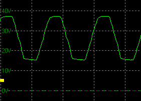
| (6.4 ms/div) | ||
| 7824 input (after rectifier) |
 |
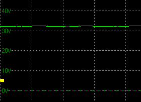 |
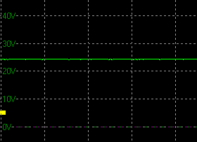
| 7824 output |  |
 |
The oscilloscope has shown this to me. It's actually quite a miracle that the amp was still passing an almost useable RF signal. The dissatisfaction on part of receivers has been growing over the last several months.
If the oscilloscope shows you something resembling a sine wave,
the elyts need to be replaced.
Start by unscrewing all the screws you can find around the PCB
(including the metric bolt in the PSU compartment). But, uh oh:
the chassis won't let go of the PCB!
The board remains soldered into position by the F-connectors'
center pins.
The coax center pins must be desoldered first, all the solder
holding them must be sucked away, in order for the PCB
to let go of the chassis. Fortunately the tiny open-ended "slots"
in the PCB are not copper-plated on the inside, and especially
the old amps were probably still soldered by leaded solder,
so it will happily melt and flow (and let you suck it all away).
Once the connectors are desoldered, perhaps you should open
the front door of the CBS734 chassis, find a bit of unobstructed PCB
and gently push the PCB out of the chassis. Don't rush it,
carefully rock the PCB side-to-side as it's inching out of
the chassis. Be careful not to break something. It's true that
the aircore inductors are theoretically not tuned for a particular
frequency (no risk of detuning) but it would still be unfortunate
if you should break something.
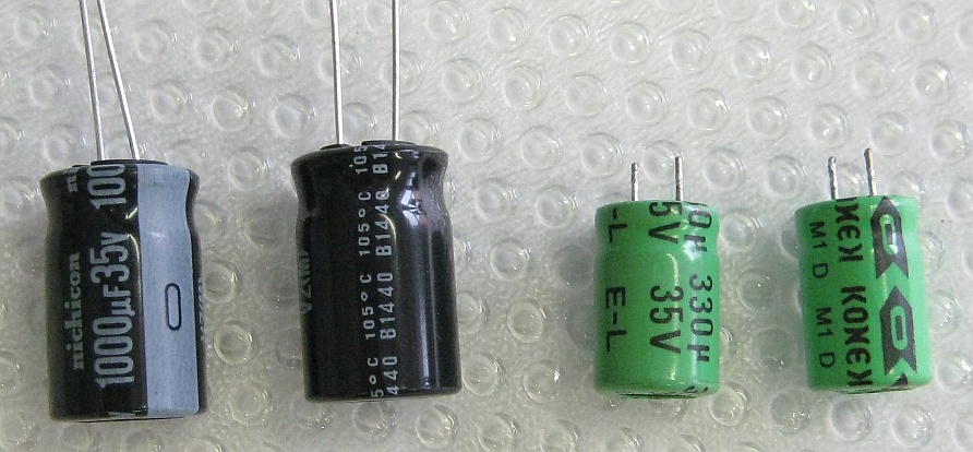
Capacitors. Originals on the right, my replacements on the left.
The capacitors are easy to desolder - the PCB pads are not too big.
Once you return the board into the chassis, don't forget to solder the coax connectors back in (my own experience :-)