Noise generator schematic - click to download a vector drawing in PDF format
This is a hobby project that I ventured a couple years ago.
Out of curiosity, and as a preparation for some tuning work on our antenna system.
During the transition from DVB-T to DVB-T2, there was a bit of a dancing performance going on in the spectrum, with frequencies and amplitudes changing over time. In my particular location, the final mix of channels is a little unfortunate. Hence the need to play with analog filters around the first preamp stage. And yes I did try to squeeze maximum "spectrum shaping" out of the passive elements of the antenna system first and foremoset :-)
As an aid for tuning LC filters and preamps, I have built this noise generator. The schematic and board presented below are actually my Version 2. The first "proof of concept" version did not turn out very well, and although it served me to learn some essential design lessons and allowed me to ballpark the gain and bandwidth of a single stage, it had too many flaws to be of practical use.
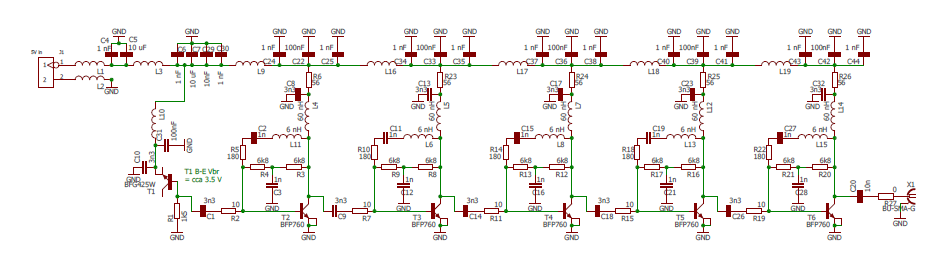
Noise generator schematic - click to download a vector drawing in PDF format
You probably get the overall idea: there's a reverse-biased BE junction of an RF transistor to produce broadband noise, followed by a nasty cascade of gain stages. The point was that if needed, I can always leave a stage (or two) unoccupied and "passed through", or I can shape the transfer curve in individual stages to produce a more uniform "spectral profile". In the end I used all the stages, and I did play with the feedback networks a little.
Why BFG425W as a noise source? Well - no dark magic, just practical reasons. In its heyday it was a reputable workhorse of an SiGe RF transistor, but with the arrival of the BFP 650 (not sure about the 760), the old 425W became yesterday's news. I had some lying around, and did not plan to use them in amplifiers any longer. This microwave SiGe technology also has a pretty low breakdown voltage - it can only work with a Vce up to about 4 Volts (BFP650), but for our purpose (noise generation) the B-E reverse breakdown voltage of about 3.5 V is convenient. The generator can work with a single rail of +5V as a power supply. About the "productivity" and bandwidth of such a noise source, in terms of "design convenience".... frankly I don't know. I figured that an RF transistor would probably produce a convenient RF noise bandwidth. Not sure to what extent this is a correct train of thought. Ultimately what matters is the end result. Check the spectral screenshots at the end of this web page.
The topology of the five stages is pretty much identical. So if I take the first stage for example:
R3 and R4 provide a filtered negative DC feedback, that should self-bias the T2 into a working range of current and voltage, where the collector of T2 acts against R6. The desired operating point at the collector of T2 is abot 2.5 - 3 V. These SiGe transistors have a higher gain at a higher Vce, but they also have a fairly low operating Vce_max. See the datasheet. Transistors from different lots will have a slightly different Hfe / threshold voltage and may need a different resistance in R4 and R3 for correct biasing.
Should you want to limit the AC gain per stage, you can use the R5 for that, which needs a DC decoupling capacitor in series (C2) = not to ruin the DC bias. Which as a side effect leaves DC gain of the stage at the transistor's maximum...
You may also want to winch the gain a little higher at the upper end of the transistor's operating bandwidth. For that, try using the L11. I've tried to crank up the gain above 1 GHz in this way - only to find out that you won't succeed to "extend" the range in this way. You will probably just form a peak towards the existing upper end, turning the amplifier into a narrow-band thing. Apparently, the gain at the upper end of the spectrum is pre-determined by other factors: the transistor's internal construction and package, package dimensions and PCB dimensions and the ceramic capacitors used for power blocking... it is probably the reason why conventional discrete transistor technology (esp. in a broadband setup) is at the end if its capabilities in this frequency range. A little bit can still be achieved by tighter on-PCB integration, then MMIC (analog microwave IC's) will take you another step further, advanced PCB substrate sure helps a little... but, yet further above (2 GHz+), all you get is on-die silicon structures. (Because anything on a PCB already acts like an inductor.)
To be honest, some time has passed since I built that noise gen, and I recall making some changes which I did not properly document.
Such as, I've probably chaged the signal coupling capacitors in the cascade. IIRC, with the 3.3 nF that you can see in the schematic, the thing had too much gain at low frequencies ("near DC") and was catching feedback through the power supply filter cascade. The generator would oscillate - I no longer recall if it was a couple dozen kHz or units of MHz. I believe that I curbed this by replacing the 3n3 coupling capacitors with something like 100 pF (C1, C9, C14, C18, C26) and after that the thing was stable.
As for the PCB:
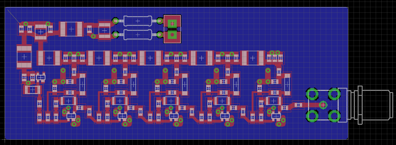
Noise generator PCB - here you are the gerbers again
The PCB is mounted inside a cast aluminum box by Gainta (I guess). I've tried to separate the gain stages a little by placing grounded metal plates between the stages. Not sure if that had some effect :-)
Most of the passives are 0603 size = makes them solderable by hand, by a soldering pen.
My substrate is 0.5mm FR4. And although it doesn't make much sense, among just a handful of transistors, I tried to keep the signal traces close to 50 Ohm impedance. As I had other uses for the noise source, apart from TV technology (which typically works with 75 Ohms Z_nom.) Also, nowadays I'd probably use a different output connector - the sort where the SMA is mounted level with the PCB. These provide a better impedance match to the PCB trace.
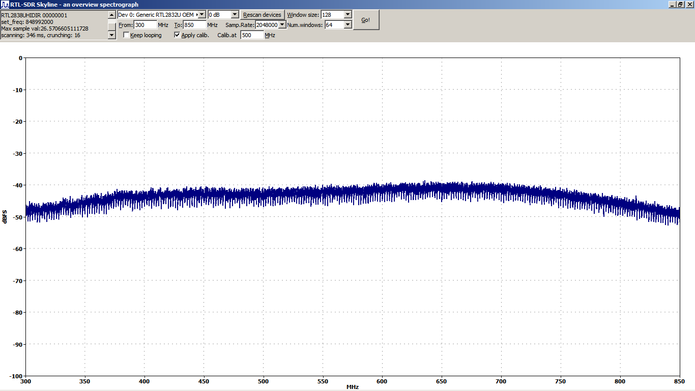
And this is what the output looks like:
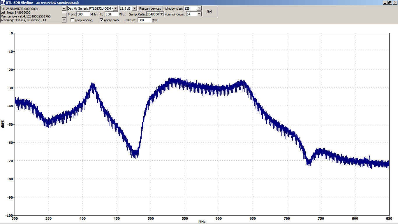
The following is an example of a TV antenna filter that I've built using this noise generator:
By: Frank Rysanek [Frantisek DOT Rysanek AT post DOT cz]
Built in 2020, published in 2024